In this article I want to show you how I build my modules step by step. This is especially adressed to people who are just starting out and to increase the chances to succeed. Further below you can find a list of my troubleshooting routine. So let’s dive right in.
Building synth modules with stripboards
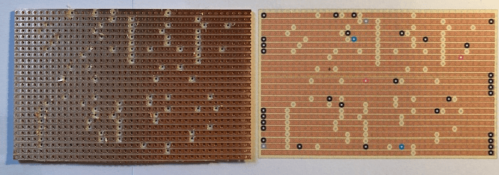
The first step is to print out the layout, if available just with the line breakers. Now I mark all the points on the board with a permanent marker and cross everything out on the printout. The points are also super useful as a reference when you put in the components. Sorry for the chipped board by the way.

When this is done, I take the mirrored version of the layout and check if I really made all the line breakers and cross them out on the paper. The breakers are done by hand using a drill bit. I also go over them with my multimeter to make sure if they really break the connection.
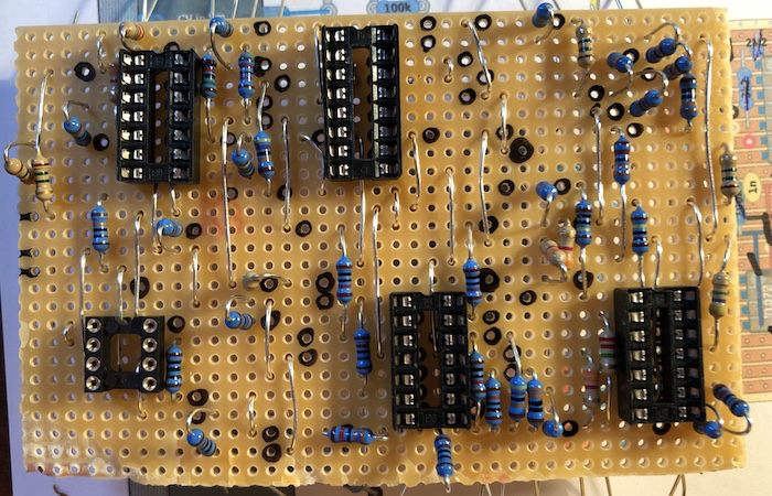
The next step is to put in all the jumper wires and IC sockets. Again, when I insert a jumper I cross it out on the printout right away. So I can make sure that nothing gets forgotten and that the positioning is right. The marked points of the first step come in handy here.

Now it’s time to put in all the resistors. I also measure every single resistor with my multimeter to avoid faulty components and just mistakes by choosing the wrong value. This might be a bit tedious but it it can safe you from a lot of headaches later. It’s almost impossible to find a wrong resistor once everything is installed. I solder all resistors in one go.

Subsequently, I insert all the other components like capacitors, transistors and trimpots.
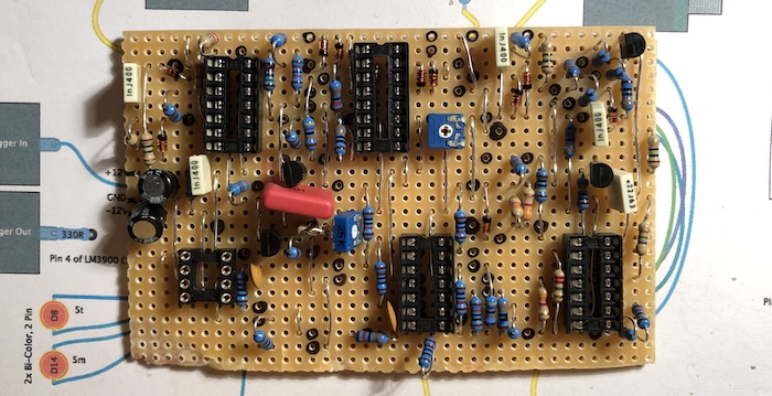
What’s left are the components on the bottom of the board. I know it’s not common but my layouts got those to make them more compact. I also recomment to solder decoupling capacitors between all power pins of all ICs and ground. Cheap 100nF cereamic capacitors are ideal for that task. It is important to have them as close as physically possible to the pins and you can’t get any closer, than doing it straight from the bottom. The decoupling caps filter out any voltage fluctuations that might come from your power supply. Also solder in some electrolytic capacitors right behind the power connection of the board. 10µF or 22µF are a good choice here. One of those is between V+ and ground (negative pole to ground) and the other between ground and V- (negative pole to V-).
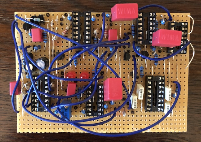
The last step on the boards are the jumper wires.

Okay, a big portion of the work is done, time to equip the panel! I screw all potentiometers, switches and jacks in. That makes soldering easier. For proper grouning I just use some bare wire soldered to all points right behind the panel. Same for V+ and V- connection. I just put in one single wire from those connections to the circuit board. This not only makes wiring easier, you also don’t have the risk of getting a ground loop. Trust me, you don’t want to have a ground loop. To increase the chances that the module works first try, I go over all the strips with my multimeter in continuity-mode and check for shorts, caused by little solder whiskers, between the lines. If yours don’t got that mode just measure the resistance. If it is around 0 Ohms you discovered a short.
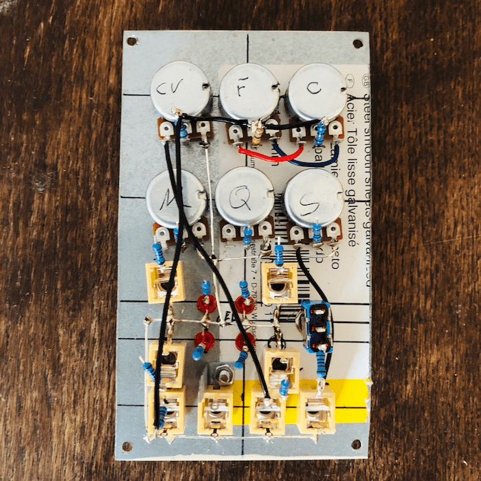
Wedding-time! On of the last steps is to put the panel and the circuit board together. Now it looks like a module right?
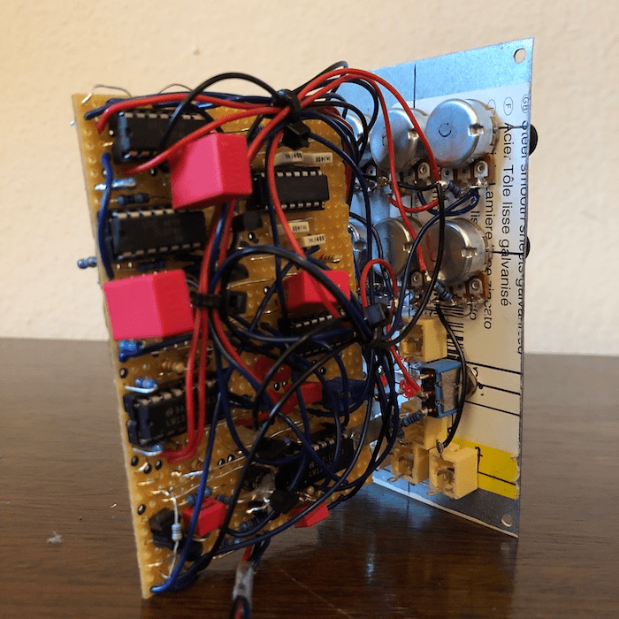
When I power the module up for the first time, I leave all the ICs out and check, if the right voltages are on the power pins. Just use or multimeter for that by putting one probe to ground and the other to the spot on the IC socket where the power pins will be. If all voltages on the V+ and V- destinations are correct, you can put in the ICs.
Now the module is done! But what if nothing comes out or it behaves strange? Uff… troubleshooting.
My troubleshooting routine
- Print the layout out again
- Check if every component is in the right spot and cross it out
- Look for components that touch each other on the top side of the board by mistake
- Make sure all the line breakers are there and if they really break the connection
- Measure the cotinuity between the panel parts (potentiometers, jacks, …) and the circuit board. Is everything grounded? Go all wires to the right destination?
- If you have switches, check if they work properly with your multimeter in continuity mode
- Measure the voltage on the power pins of the ICs again
In my experience, most of the trouble was caused by random short cicuits between the strips or line breakers which didn’t fully broke the connection. If you experience that semiconductors are getting hot at the first test, they might got damaged and need to be replaced. I’ve also heard that some people got problems with fake chips. Swapping out the ICs is also one thing to try. But this was never the reason for malfunctions in my builds – always my own mistakes.
Alright, that’s it! If you got any questions or if you think that something is missing here, just leave a comment below or come over to my Facebook group. Thanks for passing by and every feedback is highly appreciated!
