Vacuum Tube Synth

Disclaimer
This project includes high voltages which can be dangerous if not lethal. Only attempt this build if you are experienced and well trained in electronics. I take no responsibilty for people who get injured while working on this project. Build it at your own risk.

This project was insane. I had the idea of building the old Metasonix TS modules in my mind since two years. Since these include the work with higher voltages I wanted to gather a solid understanding of electronics and schematics before I attempted this project. In January 2022 I finished my solid-state synth and now I thought I just need to go for it. In this article I want to talk about the experiences I made, how I did the things and what lessons I’ve learned. I’m not going to share my protoboard layouts for three reasons. The first one is that you need to be able to read schematics and to work with those when attempting a project like this. The second is that I’d strongly recommend to use turret boards instead of protoboards for the circuitry or to take the elegant route by designing you own pcb’s. This will make it way easier to assemble this device. The third one is that I’ve made some changes to the layout while working on them.

This article will be a bit longer. Here is the table of contents if you want to jump to specific part:

The Idea

I was always interested in vacuum tubes. Coming from the guitar and bass guitar world it was always the best choice to use a tube amp – eventhough they are pretty expensive. Over the time I was wondering why tubes are so rare in the synth universe. Of course you got some pioneers like Friedrich Trautwein who has created the Trautonium for example. Nowadays most synth companies use tubes with low-voltage, which is nice too! And there is one exotic folk, Eric Barbour, who just designs super interesting synth modules – following his principles of making unique and non-standard audio devices with vacuum tubes.

Since this project includes to work with high voltages it was important to me to gather enough experience with electronics. I’m also coming from an engeneering background with a masster’s degree in renewable energies. A big portion of it was electrical engeneering. I’m also used to work with mains voltage in my job. It is important to know what you do when working with vacuum tubes. After I successfully built some complex modules by translating their schematics to stripboard and did enough reading about vacuum tube electronics it was time to attempt this project.

Power Supply and Case

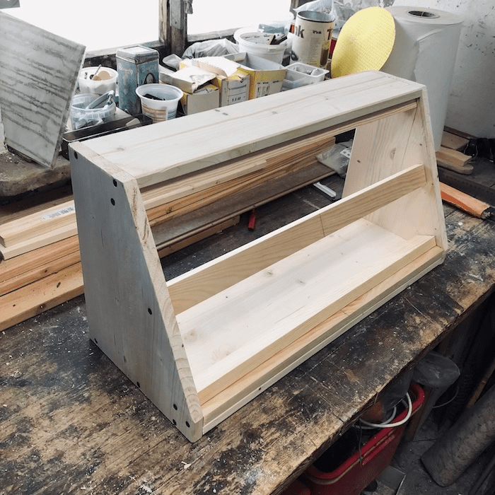
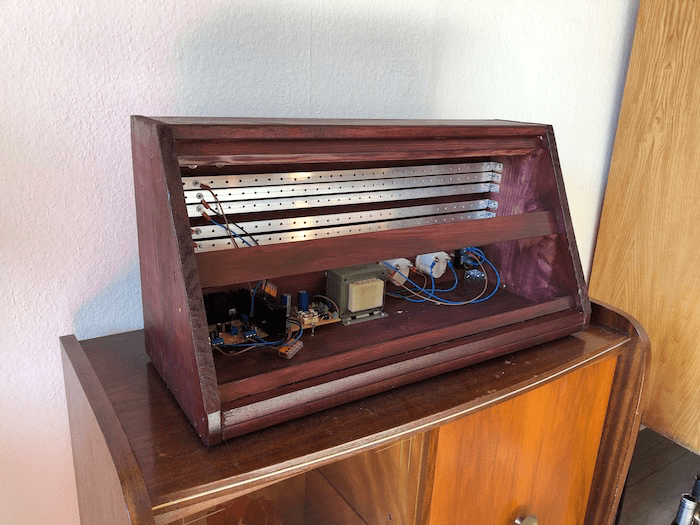
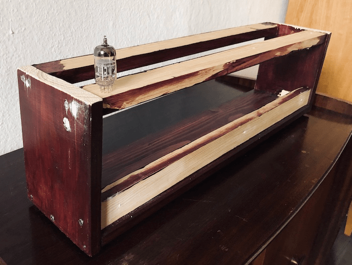
The first thing was to make a case and a power supply. Fortunately I already got a wooden box lieing around which was used for my first diy modular synth. I cut it a bit smaller and modified it a little.

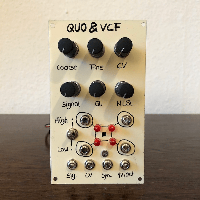
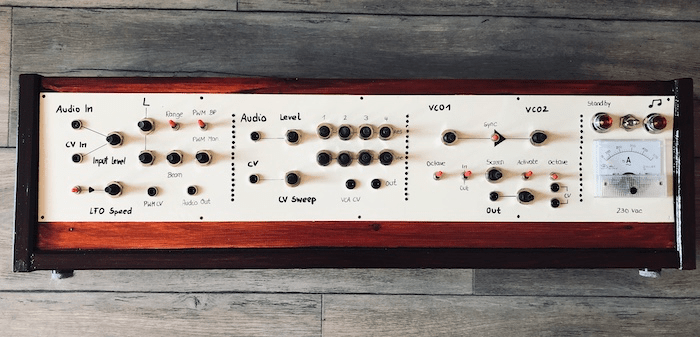
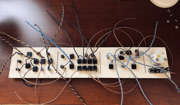
I’ve made the panel like always using sheet metal from the hardware store, drilled all the holes, spray-painted it and put all the potentiometers, jack sockets and switches in. Then I soldered all the wires to it. As you can see, I also equipted the panel with an analogue amp meter. The idea was to visualize the tubes heating process. When the tubes are cold and get switched on you get a pretty high inrush current which is getting smaller when the temperature of the filaments increases. To reduce the current draw in that phase I also decided to build in a stand-by switch. When it’s in standby, only the tubes filaments get voltage (6.3 Vac). When the switch gets flipped over the rest of the circuitry is set under voltage.

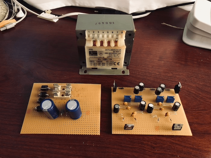
After this was done it was time to build the power supply. In this project we got 13 tubes in total. Most of the power consumption is drawn by the filaments. To know which transformer to choose I had a look at the datasheets of all the tubes which will be used. In the datasheets you get the info of the current draw of the filaments in the state of operation – when they are heated up. In total all tubes consume around 4.8 A at 6.3 Vac. Make sure to use thick enough wires here. Since the inrush current can be 3 times as big while they heat up after the device is getting switched on, the transformer needs to be able to deliver at least 15 A at the 6.3 V secondaries. The transoformer I got is the Hammond185F12. It is dimensioned for 130 VA and got two 6.3 V secondery windings (20.6 A). This is more than enough to power the tubes heaters and the circuitry. The second secondary goes to a second tranformer which has two 115 V primary windings and two 6.3 V secondaries (only one of those is used). The second secondary of the first transformer is wired to one of the secondaries of the second one, which is wired in backwards so to say. For the second transformer I’ve choosen a Hammond183K12. It is super important to install fuses before the first and between the transformers. If you skip this you get the risk of burning your house down when something goes wrong.

This is the layout of the power supply:

The rectification is done with an E91AA tube. You can also use rectifier diodes configured as a full bridge rectifier here. After the RC filter we get 113 Vdc for the circuitry. For the circuitry all resistors are rated for 2 W and all capacitors for 450 V (250 V is also enough).

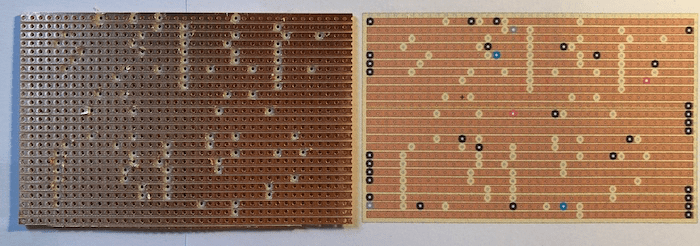
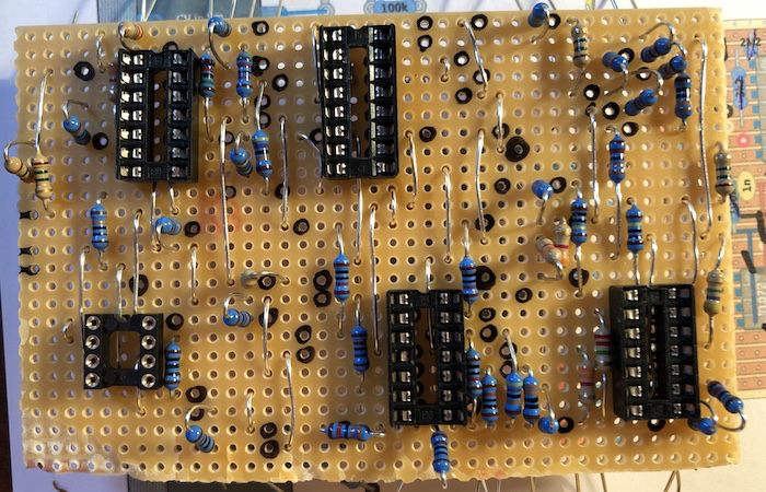
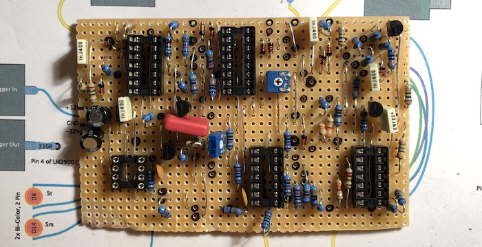
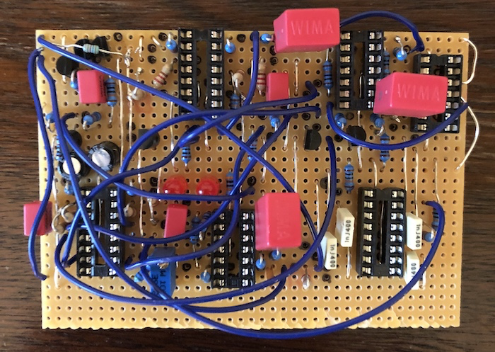
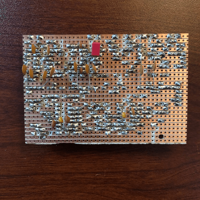
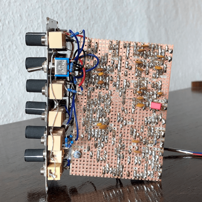
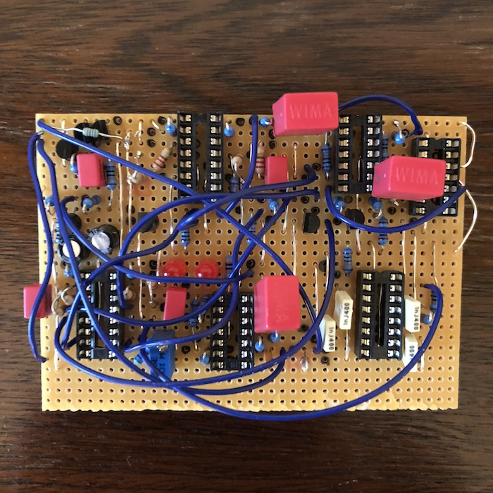
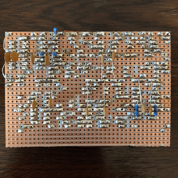
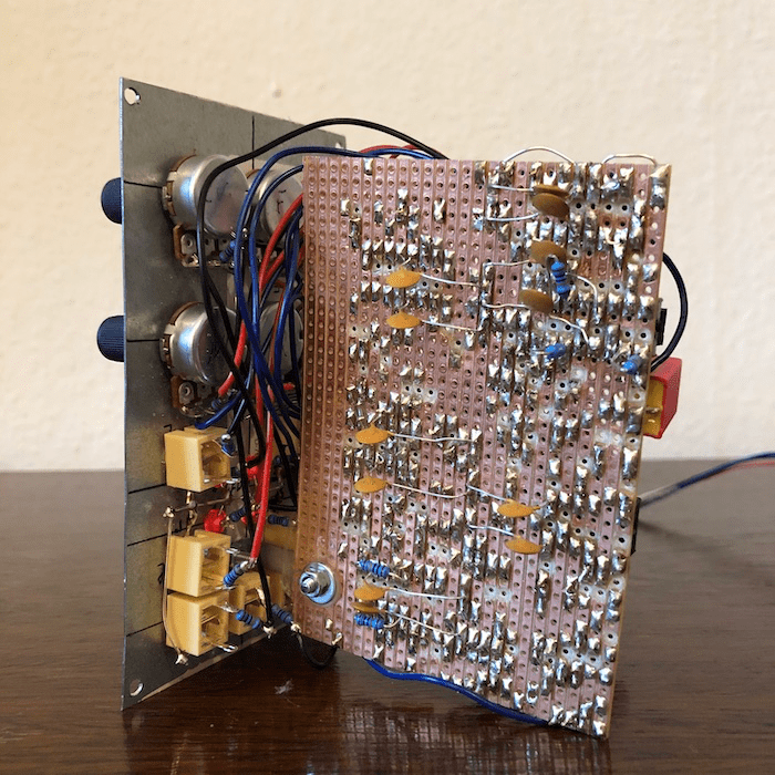
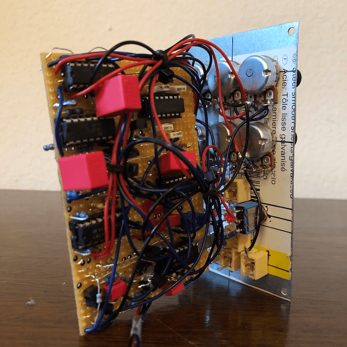
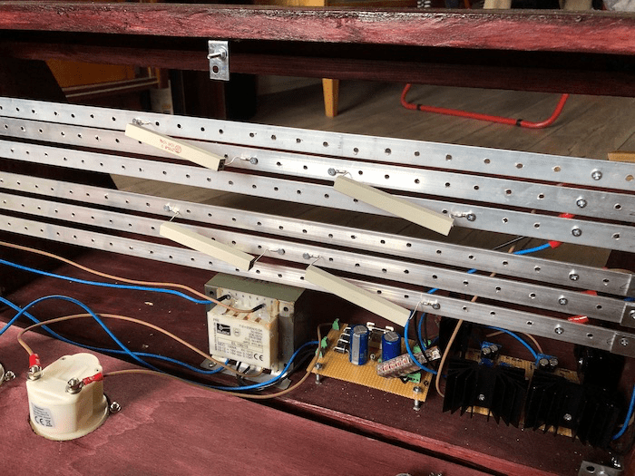
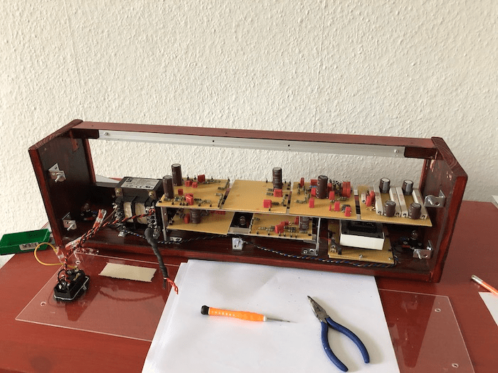
The circuitry is done on protoboards which are mounted to an internal metal chassis. Apart from just holding the circuit bords it also shields the circuitry from the electromagnetic fields of the transformers and provides the central star-point of all the ground connections which finally go to mains earth. Here is a good read about proper grounding techniques with vacuum tube circuits. In retrospective I’d use turret boards instead of proto boards. This would have made the installation a lot easier.

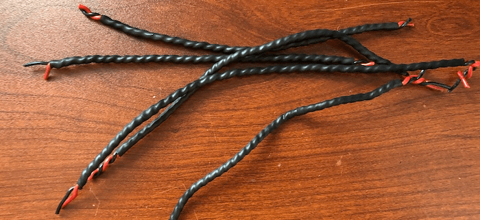
What’s also important is to twist the wires which are carrying AC voltage to reduce the risk of getting the 50 Hz mains hum into the signal path. I just put the wires into my drilling machine, twisted them up and put some heat shrink sleeves around them. Here you get some good information addressing this subject.

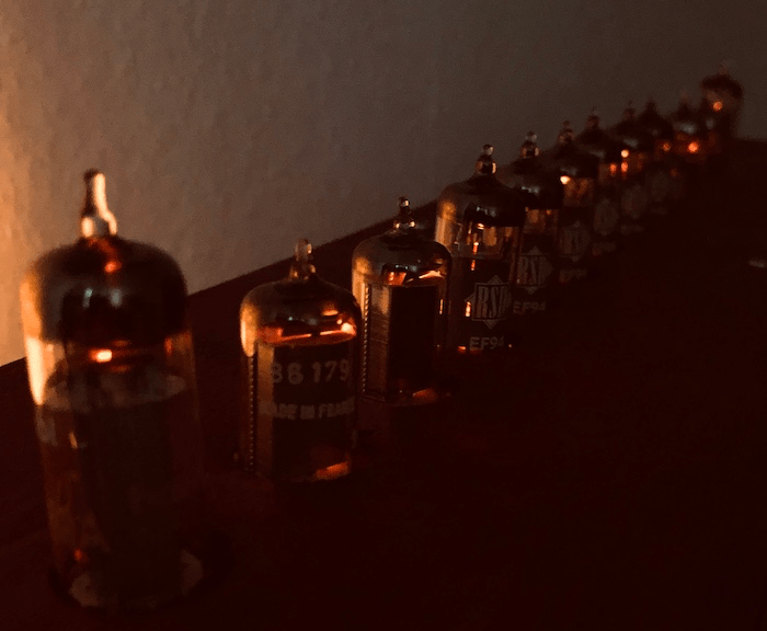
The next step was to install the tube sockets to a piece of sheet metal and to solder in all the wires.

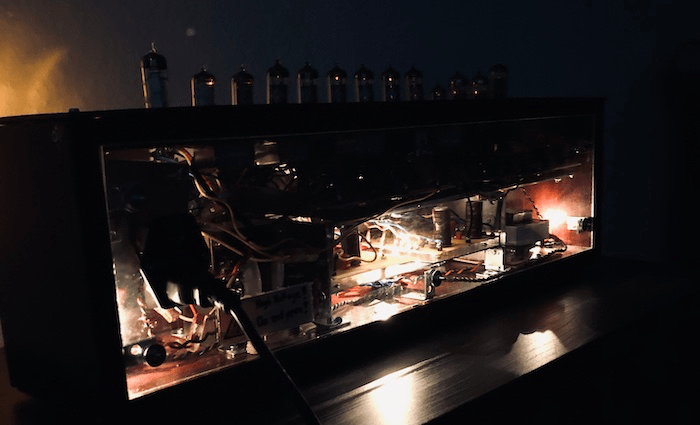
The case also got three 6V light bulbs to make it a bit more shiny:

I know it can also be difficult to source tubes and such. This is the retailer I used here in Germany. Here I got the transformers and all the tubes.

Metasonix TS-21

It’s hard to describe what the TS-21 Hellfire Modulator is and what it does. So I just summarize the information from the original source. Definitelly a pretty gnarly sounding thing!

The Hellfire Modulator consists of two independent effects units. The first one is a PWM circuit acting as a monostable multivibrator – a metastable circuit. The switch point of this circuit can be changed with the PWM panel potentiometer. Best practice is to feed it with sharp waveforms like saw or square.

The second one is the beam modulator with a tube origanilly intended for applications in TV’s. By electrostatic deflection the signal switches between two anodes, which results in a stereo output. You can also plug in a mono cable – getting a mono output. Last but not least it also has a built in LFO which can be switched off.

What’s also important to mention is that the labeling of V3 and V4 is reversed in the schematic! So V4 and V5 should be the same instead, not V3 and V5. Another useful tip I found in a post on wiggler is to put a 100k resistor between pin 6 of V4 and V5 and ground. Here is the schematic. I also figured that there was only a tiny useful bit on the L2 potmeter. I swapped it for a 500k instead of 2M5 and put a 2M resistor between point W of the schematic and the potmeter. I would also recommend to use an even smaller potmeter like 100k. You can experiment here, just keep in mind that you get 2M5 in total. This device needs also some time to understand and some dead spots are normal. It needs waveforms with discontinuities like saw or square waves. If you put a square signal into the signal and PWM input you can have a lot of fun with it. Hint: experiment with the pulse width and the frequency of your incoming signals. The Hellfire Modulator really lives up to its name!

Okay, enough talking, here is how it sounds:

Here are two other demos, not mine, which I found on Youtube:

Metasonix TS-22

The TS-22 Pentode Filterbank was a total secret to me. I wasn’t able to find any information, like demos, for that device.

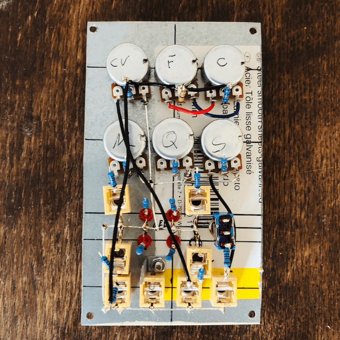
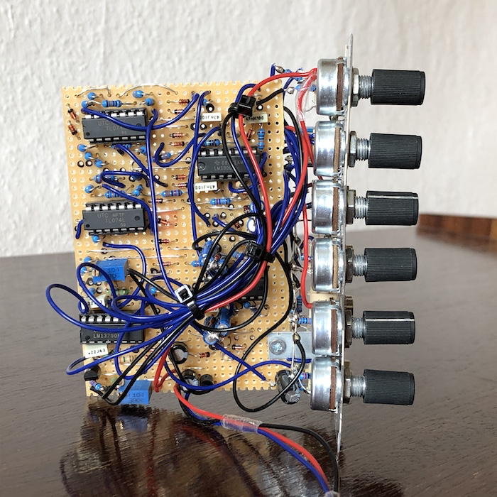
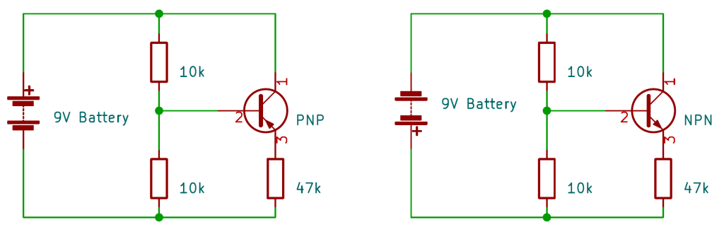
It consists of four independent bandpass filters with separate resonance and tune controls each. They mix down to a VCA. Each filter is based on a pentode tube with a simple Twin-T circuit. The CV is driven by a little opamp circuit. The schematic does not explicitly tell the pin numbering of it. So I asked my friend Eddy Bergman and he just passed over this little sketch. Thanks! I used a TL071 for it, since this is what I got in stock already.

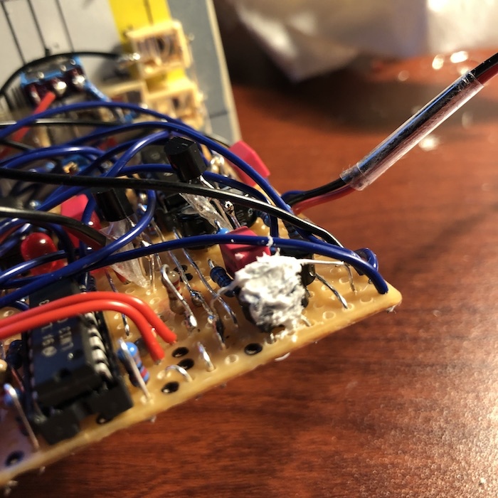
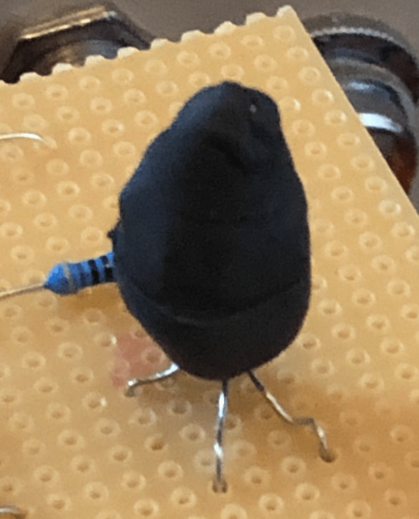
The tricky part here is that you have to make a quad vactrol consisting of one LED and four LDR’s. I’ve choosen a white LED and the specs of my LDR’s are 50k-160k/20M. I matched them by switching on my desk lamp to get a consistant light source and took the four with the most similar readings. Then I crammed them together with some heat shrink sleeves and a little hot glue. I was lucky and it worked out from the get go!

I couldn’t find a single demo of it, but here is how mine sounds. Maybe it’s the only demo in the world wide web. Happy how it turned out!

Metasonix TS-23

The TS-23 Dual Thyratron VCO sounds unlike any other VCO I’ve come across. Each oscillator is based on a 2D21 tube which acts like an instable switch allowing a capacitor to charge and discharge. The cycle of this process can be adjusted with the tune potentiometer, thus changing the pitch of the sound you’re listening to. It delivers a saw wave that isn’t perfect. This results in an unique and pretty raw tone.

Another feature of it is the beam modulation. This results in a squishing effect, based on a very nonlinear waveform clipper. But I couldn’t get this portion to properly work yet.

Again, this circuit is driven by a little opamp circuit and the schematic doesn’t tell the pinout. Kindly Eddy sent me another quick sketch to make it clear. I used a TL071 like with the TS-22. It worked also right away but I haven’t really tuned it yet.

And there is still another problem. The level of oscillator 2 is way lower than of oscillator 1. This can be solved by tweaking some resistor values, but I leave it for now.

Here is how my TS-23 sounds:

Here is another demo from someone else:

Conclusion

All in all it was by far the most complex diy project I’ve ever done. I also gathered a lot general knowledge in electronics like proper grounding techniques and electromagnetic fields resulting in hum or noise. In total it draws about 55 W – 80% of it caused be the tubes filaments.

Also there was way more crafting work involved than I expected before – especially the wiring. One quote of one of the wiggler posts is definitelly on point:

“Tubes suck, okay? They do amazing things but hate you along the way.”

Again a shoutout to Eric Barbour of Metasonix for publishing his old schematics!

I’m super happy that it is in my arsenal now – a super unique piece of gear! It’s so much fun to play around with it’s gnarly sounds and it’s great that it is also compatible with solid-state synths. The combination of both is where it really starts to shine!

That’s it for know. Thanks for passing by! If you got any questions or feedback just leave a comment below or come over to my Facebook group. Cheers!

Build Guide

In this article I want to show you how I build my modules step by step. This is especially adressed to people who are just starting out and to increase the chances to succeed. Further below you can find a list of my troubleshooting routine. So let’s dive right in.

Building synth modules with stripboards

The first step is to print out the layout, if available just with the line breakers. Now I mark all the points on the board with a permanent marker and cross everything out on the printout. The points are also super useful as a reference when you put in the components. Sorry for the chipped board by the way.

When this is done, I take the mirrored version of the layout and check if I really made all the line breakers and cross them out on the paper. The breakers are done by hand using a drill bit. I also go over them with my multimeter to make sure if they really break the connection.

The next step is to put in all the jumper wires and IC sockets. Again, when I insert a jumper I cross it out on the printout right away. So I can make sure that nothing gets forgotten and that the positioning is right. The marked points of the first step come in handy here.

Now it’s time to put in all the resistors. I also measure every single resistor with my multimeter to avoid faulty components and just mistakes by choosing the wrong value. This might be a bit tedious but it it can safe you from a lot of headaches later. It’s almost impossible to find a wrong resistor once everything is installed. I solder all resistors in one go.

Subsequently, I insert all the other components like capacitors, transistors and trimpots.

What’s left are the components on the bottom of the board. I know it’s not common but my layouts got those to make them more compact. I also recomment to solder decoupling capacitors between all power pins of all ICs and ground. Cheap 100nF cereamic capacitors are ideal for that task. It is important to have them as close as physically possible to the pins and you can’t get any closer, than doing it straight from the bottom. The decoupling caps filter out any voltage fluctuations that might come from your power supply. Also solder in some electrolytic capacitors right behind the power connection of the board. 10µF or 22µF are a good choice here. One of those is between V+ and ground (negative pole to ground) and the other between ground and V- (negative pole to V-).

The last step on the boards are the jumper wires.

Okay, a big portion of the work is done, time to equip the panel! I screw all potentiometers, switches and jacks in. That makes soldering easier. For proper grouning I just use some bare wire soldered to all points right behind the panel. Same for V+ and V- connection. I just put in one single wire from those connections to the circuit board. This not only makes wiring easier, you also don’t have the risk of getting a ground loop. Trust me, you don’t want to have a ground loop. To increase the chances that the module works first try, I go over all the strips with my multimeter in continuity-mode and check for shorts, caused by little solder whiskers, between the lines. If yours don’t got that mode just measure the resistance. If it is around 0 Ohms you discovered a short.

Wedding-time! On of the last steps is to put the panel and the circuit board together. Now it looks like a module right?

When I power the module up for the first time, I leave all the ICs out and check, if the right voltages are on the power pins. Just use or multimeter for that by putting one probe to ground and the other to the spot on the IC socket where the power pins will be. If all voltages on the V+ and V- destinations are correct, you can put in the ICs.

Now the module is done! But what if nothing comes out or it behaves strange? Uff… troubleshooting.

My troubleshooting routine

  • Print the layout out again
  • Check if every component is in the right spot and cross it out
  • Look for components that touch each other on the top side of the board by mistake
  • Make sure all the line breakers are there and if they really break the connection
  • Measure the cotinuity between the panel parts (potentiometers, jacks, …) and the circuit board. Is everything grounded? Go all wires to the right destination?
  • If you have switches, check if they work properly with your multimeter in continuity mode
  • Measure the voltage on the power pins of the ICs again

In my experience, most of the trouble was caused by random short cicuits between the strips or line breakers which didn’t fully broke the connection. If you experience that semiconductors are getting hot at the first test, they might got damaged and need to be replaced. I’ve also heard that some people got problems with fake chips. Swapping out the ICs is also one thing to try. But this was never the reason for malfunctions in my builds – always my own mistakes.

Alright, that’s it! If you got any questions or if you think that something is missing here, just leave a comment below or come over to my Facebook group. Thanks for passing by and every feedback is highly appreciated!

Serge SSG

This is a pretty interesting utility module with loads of functionalities to explore!

About the Module

The Smooth & Stepped Generator (SSG) consists of two sections wich are linked together by a comperator. With the smooth section you are able to add a positive and negative slew to an incoming signal. This can be used to produce lag effects, voltage controlled portamento or as a filter for low frequencies. By applying a high signal (>4.5V) into its hold input it works as a track and hold with voltage controllable slew rate. It is also an oscillator in CV and audio rate – usally by patching the cycle output to the input. I thought it would be usefull to pre-route this patch, so I just connected the switch terminals of these two sockets together. If a cable is patched into one of them, it is disconnected. If you want to build it true-Serge by using banana sockets, you can add a cycle switch (SPST or SPDT) to add this function. I also added this to the stepped section.

The stepped section can be used as a sample and hold with voltage controlled slew rate limiting. To generate complex staircase functions (in cycle mode), feed the hold input with a square signal.

With the coupler you are able to generate random voltages or complex controll voltages. It compares the output signals of the smooth and stepped section.

My Build

First of all, you can download my stripboard layout, the BOM and schematic with the following link. I used it for my own build.

serge_ssg.pdf

It took me a little effort to get this module going. At first I messed up the power connections of the LM3900’s. From previous builds and from the datasheet I was used to tie pin 7 to ground. In this module it has to be connected to V- instead. As this was solved I discovered that there need to be some modifications applied to make it properly work with a LM13700 instead of two CA3080. The CA3080 is no longer in production and hard to find. It is possible to get but relatively pricy. The two 82k resistors need to be swapped out by 150k’s and there need to be two additional 150k resistors to be added to each of the LM3900’s. Also one of the 1nF caps should be increased to 2.2nF. I added these modifications to the schematic to make this clear. After this was solved too, the smooth section worked like a charme. The stepped on the other hand… So back to the bench. I discovered a missplaced resistor and boom! It was working!

Also the J201 JFETs aren’t that easy to find as through hole components. I was lucky to have a retailer here in Berlin that got those in stock. On the original source it’s mentioned that most general propose JFETs should work, same with the PNP transistors. So try whatever you already got or can get easily. Just make sure the pinouts fit by comparing it with the schematic.

Here are some pictures of the finished product:

Calibration

You got one trimmer for each section of the SSG. The left one on my layout is for the smooth and the right one for the stepped section. An oscilloscope can be handy but you can also calibrate it by ear – so did I. To calibrate the smooth side it needs to be set in cycle mode, which is already pre-patched in my layout. Now turn the the rate pannel potentiometer to maximum. You will get triangle signal in audio rate. The trimmer changes the frequency of this signal. From a certain point you wont notice a change anymore. This is the point where it’s calibrated.

The stepped side needs also to be set up in cycle mode. In addition, you need to put a high frequency square wave into the sample input – otherwise it won’t cycle! Now it’s the same procedure as before. Turn the rate potentiometer to the maximum and find the spot from where the trimmer has no influence on the frequency anymore.

Now you are done and ready to role!

Patching Techniques

This module can be a little overwhelming at first and it is definitely not self-explanatory. I found this threat on Wiggler where someone cited an old yahoo-post. As you can see, the SSG offers loads off functionalities to explore and has lots of hidden secrets!

If you like what you see or got any feedback just leave a comment below or come over to my Facebook group. Thanks for tuning in!

Serge Wave Multipliers

In this article I want to show you some snippets of my building process of the Serge Wave Multipliers (VCM).

About the module

This module consists of three sections. The top one is the simplest of these. It can be used as an ordinary linear gain controlled VCA by setting the switch to the low mode. The high mode squares up the incoming signal. The effect you get from it is similar to an overdriven tube amplifier, but voltage controllable.

The second wave multiplier comes with two inputs to mix two signals. By turning the potmeter up you get odd harmonics so you can make a boring sine wave more interesting. The amount is voltage controlable. You will get awesome sounds from it!

The wave multiplier at the bottom produces even harmonics and has also two inputs. It kind of sounds like a distortion. It also has two outputs where one of them is the squared up version of the other. It can produce pretty harsh sounds.

The building process

As always, my stripboard layout is pretty densly populated. This is because I like to build my modules compact to make the most of the available space I got. I also try my best to fit all the components on one board. I used the following layout for my own build. You can download the high resolution layout and schematics here:

serge_wave_multipliers.pdf

The schematic of the third multiplier calls for three 1µF bipolar capacitors. These don’t count as a standard part in the stock of general electronics retailers though. However, there is a workaraound to that problem. Kindly, Eddy Bergman sent me an easy schematic on how to build bipolar caps with higher capacitance on your own. You can of cause also use polyester caps. This is how it works:

I just soldered the caps and diodes point to point and this it how it looks like:

Calbration

The calibrtion of the top and middle wave multiplier is pretty straight forward. Just put an audio signal into the CV input and turn the CV potmeter all the way up. You will hear the signal coming through. Now turn the trimpot until you can’t hear the signal anymore. I used multiturn trimpots since that’s what I got in stock. You can also use single turn ones. There is even a video showing how to do it:

Here are some pictures of my build:

When looking around in the internet, I noticed that there aren’t really any easy demos of it availlable. To get you an idea on how it sounds I recorded my own. As you can see, the third multiplier is folding the sine wave although the potmeter for the folding amount is turned all the way down. I don’t know if this is normal, but for me it’s no problem.

That’s it. If you like what you see or if you got any questions or feedback just leave a comment or come over to my Facebook group. Thanks for tuning in!

Transistor Matching (easy)

In this article I want to show you a pretty easy method on how you can match transistors. The first module I came across this procedure was the Moog Ladder Filter. Other ones that come to my mind are: Thomas Henry 555 VCO, NLC Feague, Yusynth Quad LFO.

At first I didn’t really know what to do. So I did some research in all the Synth DIY Facebook groups. I also found this circuit by Ian Fritz, which allows you to match transistors super precisely and provides additional info too. However, it comes with some drawbacks. You need to use a dual power supply and you have to match the 100k resistors punctiliously. It’s definitely more accurate than the method shown in this article. By comparing the transistors at the same time you reduce environmental influences to your measurements and the uncertainty which comes with your multimeter itself, for example. I tried that one out too, but I never got the voltage to be stable – don’t know which mistake I made. On the other hand, I always got good results with this simpler version. Most synth circuits don’t require such a high grade on precision. Also keep in mind that nowadays manufacturing processes are well optimized. If you compare transistors from the same batch, you’ll notice just a minor difference between them.

Fortunately, someone in one of the Facebook groups came across with a way easier solution. For that, all you need is a 9V battery and three resistors. The following schematics show that circuit, both for PNP and NPN transistors.

All you have to do is to connect two 10k resistors between the plus and minus pole of the battery. Their midpoint goes to the transistors base. The emitter is connected to the plus or minus pole, depending on the transistor type, in series with a 47k resistor. The collector goes straight to V+ (PNP) or V- (NPN). The idea is to bias the transostors with around 100µA. With a 9V battery you get 85µA.

It is important that you don’t touch your transistors with your fingers. The temperature change caused by that will alter your readings. Just use some pliers to put them in. To avoid changes of your room temperature and the batteries voltage due to discharge, do this procedure in one session. The batteries voltage isn’t critical. I myself use a rechargeable 9V block that actually just delivers around 7.5V. It’s just important to make sure that this voltage is constant.

Now just measure the voltage over base and emitter (Vbe) with your multimeter in DC mode. Let the transistors sattle for about 10 seconds before measuring. If you want to be on the safe side, wait a bit longer. Write the results down and if you get the same value for two, you got a match! That’s it!

Since you’ll need this in various modules, I’d recommend to build a permanent version on a small piece of stripboard. It’s handy to have it lying around whenever you need it. Here is the layout I built:

And that’s how it looks in real life. For convenience, solder in some IC sockets where you can put in your transistors. On the other side of the socket you are able to do you measurements with you multimeter easely. However, I’d also recommend to use that type of socket you see below my stripboard. That will make swapping the transistors out more effortless.

If you like what you see or if you have any questions, just leave a comment below or come over to my Facebook group. Here you’ll stay up to date too.

Thanks for tuning in!

NLC Feague

This module is really something else. I came up with the idea of building it since I wanted to include a sync option in my quad LFO. So I googled a little and found a post on Wiggler where this question has already been asked. Yves himself answered, that it’d hard to implement a sync option into that circuit. The reason is the time it needs to get into self-oscillation.

So I asked in a facebook group if anyone has an idea. Someone told me to have a look at the Feague by nlc. Luckily there is a schematic available and I instantly went for it. The sync option, however, acts more like freeze. It stops the oscillation as long as you send a gate signal into it. Just put whatever signal you got into it and you have lots of potential to get awesome sounds out of it!

The module itself is a quad VCO, LFO and VCF. Lots of functionalities in a small package. The 1V/Oct tracking works great over five octaves and is stable too. To achive that, it’s important to match the transistors and to use a 1k tempco, which needs to be thermally connected to the transistors. Use some thermal paste for that and make sure that the paste itself isn’t electrically conductive. Just to avoid a short. If you don’t need precise 1V/Oct tracking just use a normal 1k resistor. You don’t even have to bother about matching the transistors.

The trimpot is used to get the correct 1V/Oct tracking. Just hook the module up to a sequencer or keyboard and play two notes at different octaves. I went for C1 and C4. Now just turn the trimpot until you got it in tune. That’s it!

I used the following stripboard layout for my own build. Here you can download the high resolution stripboard layout and schematic: nlc_feague.pdf   

Here are some pictures of my build:

I also want to record some demos of it. So stay tuned! 

My Journey

Hey guys! In this article I want to show you my journey in the world of diy modular synths from the beginning to where I am now. The first thing I soldered together was a kit for a guitar pedal and that wasn’t successful. So I got another one some time later which worked out. After that there was a long break of building stuff.

Then I a saw a video of Sam Battle, look mum no computer, where he went through all the functions of his diy modular synth. I instantly got fascinated by the machine itself and the fact, that it’s possible to build something like that by yourself. Two years or so went by and I gave it a shot, finally.

The first project I’ve build was the auduino by notes and volts. I already got a little stompbox case from my first failed guitar pedal build with the exact amount of holes in it – perfect! I ordered all the parts and built it. By following the tutorial on youtube it worked first try. Later I turned it into that little sequencer. 

Now I wanted to get more serious and build a real modular synth. First thing was to build a case. I just made a sketch on a piece of paper and tinkered around what size it should have. Of cause it was important to set the size for my future panels. I went to the local hardware store and had a look what sheet metal was available. They got 20x100cm and 12x100cm. Now a had to choose between the KOSMO format or the smaller 12cm version and I went for the smaller one, since I wanted to keep it compact to make more of the available space I got. Now it was time to build the case. I just screwed together some wood and here is the result.

Now there had to be a power supply. I didn’t want to build one on my own as a first project with nearly no experience. That’s also what I recommend for beginners. Luckily Behringer just launched the CP1A psu that provides 1A on + and – 12V for just 50€. Of cause it’s no high end psu, but with 1A you can get a long way and I never had any problems with it.

Now I got a case and some juice. Time to build some modules! My first project was the simple CEM3340 VCO stripboard version by Sam Battle and I build two of them right away. Both worked first try and it was an awesome feeling to finally be able to make some noise. But I never got them to track 1V/Oct.

Now I wanted to have some modulation and built the LFO by Niklas Rönnberg followed by the VCF and mixer by Sam Battle.

Finally, I discovered the website of Eddy Bergman, which was a goldmine to me! It’s the source of most of my modules. So time went by and I just couldn’t stop building. Here is the result after about a year. I also wanted to have some more beautiful panels, so I gave them a finish with some spray paint. The labeling was from now on done by my girlfriend, since my handwriting looks like I was still in preschool. Thanks to Anne!

As you can see there was not much space left and I got so much more ideas on what I’ve wanted to do next. I also was now confident enough to build my own psu. I wanted to have one with a good and heavy transformer which will provide more than enough of clean power: 2x15Vac with 3.25Amax on each secondary. I also used the schematic by Eddy Bergman for that and combined it with the Hinton approach, using aluminum rails for the power distribution. I also built another case.

To see if I can trust my freshly built psu I gave it a little stress test. For that I calibrated both regulator boards to +-12V and put some 17W power resitors over the rails. By Ohm’s law you get 1.2A on each regulator (I = U/R; I = 12 V/10 Ohm = 1.2A). Also keep in mind that you have to stay below the power rating of your resistors (P = I * U = 1.2 A * 12V = 14.4 W). They get really hot, so don’t burn your fingers. The regulators itself are designed to withstand 1.5A and it’s important to use some heatsinks. I left it on for two hours and it passed the test!

That heralded the next chapter. Now I moved all my modules into the new case, built some new, and that’s what it looks like.

I also got a Keystep Pro, which is an awesome sequencer that’s perfect to control your modular. It definitely burns a hole in your pocket, but it’s worth it. For the output and as a headphone amplifier I got a small mixer (Mackie Mix5) and some headphones (Superlux HD-681). For recordings a use the Scarlett 2i2 interface.

I’ve learned a ton about electronics during the building process. Many hours went into troubleshooting. That can be frustrating but it’s the best teacher too. I started out building stripboard layouts if I was painting by numbers. Now I’m able to design my own and I know what to do if I got a malfunctioning module. Patience and fun are definitely the most important factors in this hobby.

Now it’s February 2022 and my case is full and finished. The last projects were the NLC Feague, Serge VCM and Serge SSG. This was the first time for me to really make some more complex modules from stratch and transfer them into a stripboard layout. So cool it worked out!

Now it’s time to make a dream come true which I’ve had in mind for a long time now – the old Metasonix modules TS-21, TS-22 and TS-23. I’ve dived deep into to the history on wiggler, youtube and what not. But information to these deviced, like demos or building experiences, are almost not available! I like the attitude of Eric Barbour and Matesonix and I just want to experience the results of his work from the early days of his company by myself. The only possibility to do that is to build it on my own, since he just made a hand full of those back in the day. By now (Jan. 2022) the case is already done and I ordered all the parts I need to tackle this project. I recycled my first case for that. I’m so stoked on how it will turn out!