In this article I want to show you a pretty easy method on how you can match transistors. The first module I came across this procedure was the Moog Ladder Filter. Other ones that come to my mind are: Thomas Henry 555 VCO, NLC Feague, Yusynth Quad LFO.
At first I didn’t really know what to do. So I did some research in all the Synth DIY Facebook groups. I also found this circuit by Ian Fritz, which allows you to match transistors super precisely and provides additional info too. However, it comes with some drawbacks. You need to use a dual power supply and you have to match the 100k resistors punctiliously. It’s definitely more accurate than the method shown in this article. By comparing the transistors at the same time you reduce environmental influences to your measurements and the uncertainty which comes with your multimeter itself, for example. I tried that one out too, but I never got the voltage to be stable – don’t know which mistake I made. On the other hand, I always got good results with this simpler version. Most synth circuits don’t require such a high grade on precision. Also keep in mind that nowadays manufacturing processes are well optimized. If you compare transistors from the same batch, you’ll notice just a minor difference between them.
Fortunately, someone in one of the Facebook groups came across with a way easier solution. For that, all you need is a 9V battery and three resistors. The following schematics show that circuit, both for PNP and NPN transistors.
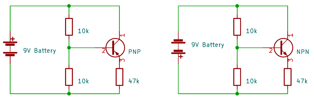
All you have to do is to connect two 10k resistors between the plus and minus pole of the battery. Their midpoint goes to the transistors base. The emitter is connected to the plus or minus pole, depending on the transistor type, in series with a 47k resistor. The collector goes straight to V+ (PNP) or V- (NPN). The idea is to bias the transostors with around 100µA. With a 9V battery you get 85µA.
It is important that you don’t touch your transistors with your fingers. The temperature change caused by that will alter your readings. Just use some pliers to put them in. To avoid changes of your room temperature and the batteries voltage due to discharge, do this procedure in one session. The batteries voltage isn’t critical. I myself use a rechargeable 9V block that actually just delivers around 7.5V. It’s just important to make sure that this voltage is constant.
Now just measure the voltage over base and emitter (Vbe) with your multimeter in DC mode. Let the transistors sattle for about 10 seconds before measuring. If you want to be on the safe side, wait a bit longer. Write the results down and if you get the same value for two, you got a match! That’s it!
Since you’ll need this in various modules, I’d recommend to build a permanent version on a small piece of stripboard. It’s handy to have it lying around whenever you need it. Here is the layout I built:

And that’s how it looks in real life. For convenience, solder in some IC sockets where you can put in your transistors. On the other side of the socket you are able to do you measurements with you multimeter easely. However, I’d also recommend to use that type of socket you see below my stripboard. That will make swapping the transistors out more effortless.

If you like what you see or if you have any questions, just leave a comment below or come over to my Facebook group. Here you’ll stay up to date too.
Thanks for tuning in!
